Nitromat nitrogen generator system is intended for use in industrial applications only.
Upon receiving your Nitromat nitrogen generator system, inspect the unit thoroughly for signs of damage. Any signs of damage, either external or internal, should be noted on the delivery receipt, and also reported immediately to both the Freight Company and OXYMAT. Contact OXYMAT at Tel +45 4879 7811 / Fax +45 4879 7813 or Tel +421 32 779 0123 / Fax +421 32 779 0125.
The owner of the Nitromat nitrogen generator system is responsible of keeping all the Important: equipment in safe working order. Parts and units must be replaced if they are no longer in safe working condition. Installation of equipment and assembling to other equipment must be done in compliance with current local regulations and directions.
The operator of the Nitromat nitrogen generator system must always use safe Important: working methods in compliance with current local safety regulations and directions.
In case of difference between directions in the manual and local regulations the strictest must be followed.
Use only hoses and pipes of correct size and suitable for operating pressure and fluid. Never use hoses which are frayed, damaged or worn. Always use the correct type and size of connections. Make sure hoses are depressurized before disconnecting.
Lifting lugs on columns, if present, are only for handling of the columns if they are detached from the PSA generator unit. The PSA generator unit is not to be lifted by the lifting lugs on columns or by the pipes. The PSA generator must be lifted by the skid, with a suitable lifting device operated by a certified or trained operator. Take the necessary precautions to avoid units tipping over during handling. Anchor all parts to the concrete floor by means of anchor bolts or like.
Exhaust gas from the nitrogen PSA generator can contain more than 30 % oxygen Warning: and be oxidizing. Exhaust gas must be led by piping or ducts out of the room to
outdoor atmospheric air. Failure to do this may cause serious damage, injury or death. The room where the generator is located must always be well ventilated.
Always vent nitrogen to outdoor atmospheric air. Failure to do this may cause serious injury or death due to suffocation. The room where the PSA generator is located must always be well ventilated. Avoid inhalation of gases. In case of nitrogen blow out, make sure the room is sufficient ventilated (before entering). Use self-contained breathing apparatus if necessary.
Make sure that your back-up/emergency nitrogen supply is installed with a nitrogen pressure regulator. The pressure must be max. 7.0 bar. Check valves must be fitted at both nitrogen delivery outlet form product tank and backup nitrogen outlet.
The interior of the cabinet contains electrical parts that may produce electrical hazard Warning: if not handled properly. To prevent electrical shock, care must be taken when
servicing this equipment. In general electrical installation and servicing is to be performed by trained or authorized personnel only.
The Oxygen zirconium module and especially the heater block can get very hot. Warning: Touching these parts may cause burns. The module can still be very hot even after
the module has been turned off. Always wait for at least 30 minutes before touching the module. If present the probe module is placed in the lower control cabinet.
Do not attempt to open the inspection hatch or similar unless the unit cycle pressure Warning: gauge reads zero and the rubber hose from the filter elements is disconnected to release pressure. The PSA generator columns can contain hazardous substances.
Handle only with proper protective clothing, gloves and eyewear and according to local environment and work environment regulations. In general mechanical and piping installation and servicing is to be performed by trained or authorized personnel only.
Tanks must be depressurized and purged thorough with air to remove all nitrogen Warning: before service or inspection. Always vent nitrogen to outdoor atmospheric air.
Sources of nitrogen must be positively blinded or disconnected before service or inspection. Never rely on a closed valve. Tank atmosphere must be analysed for safe oxygen content before inspection.
For safety, installation and operating etc. of compressor, air dryer unit or other auxiliary equipment refer to the concerned manuals of the equipment.
The compressor, air tank or other feed air supply and pressurized equipment must be fitted with adequate protective devises to protect against exceeding allowable limits of the concerned equipment e.g. safety relief valves. Feed air supply must be protected against exceeding 10 bar the maximum allowable pressure P(S) for Nitromat nitrogen PSA generators. For 12,5 bar(g) version is maximum allowable pressure for feed air P(S) 12 bar(g). The safety relief valves on PSA generator columns and product tank (if supplied) are solely for the protection of these components.
The following will cause damage not covered under the manufacturer’s warranty.
Feed air temperature T(O) above 40° C or below 5°C. Water, oil, rust, scale and/or other foreign objects carryover in the feed air due to damaged filter elements and/or plugged drains. The feed air quality must comply with specifications to ISO/EN 8573.1: 2010 class 2.4.1 or 2.3.1, unless otherwise stated.
Nitromat filter elements have been selected based upon their ability to function in severe operating conditions. Use of other than original equipment manufacturer filter elements could cause damage not covered under the OXYMAT warranty.
Nitromat nitrogen PSA generator cannot be disconnected from the power supply for the period longer than 6 month. It could cause damages not covered by Oxymat warranty. This period begins to count from the date of final operation test mentioned in Design Review Certificate. This type of certificate is always part of the delivery - unique for each serial number of PSA generator.
Improper behaviour as a result of inadequate qualification and knowledge can lead to substantial injury to person and property. Therefore don´t allow any activities to be performed by other than appropriately qualified personnel.
- maintenance or control operation to be performed by adequate qualified personnel only
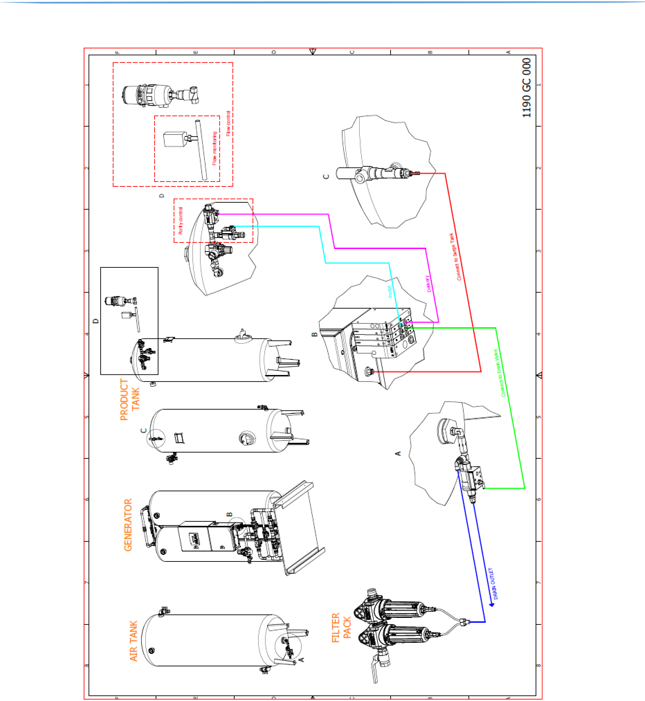
Picture 1. Layout of Nitromat Generator System
A.
B.
C.
D.
E.
F.
G.
H.
2-Column (or 3-Column or X-version) PSA generator c/w internal piping & electric cabinet
High pressure compressor – if present in scope of supply Filling ramp - if present in scope of supply
This Nitromat nitrogen PSA generator is an on-site nitrogen generating machine. Coupled with your compressed air supply or air compressor (*), it process atmospheric air and separates the nitrogen from other gases. The separation is accomplished with a molecular sieve that does not require replacement (when maintained and used according to this instruction manual). The process is completely regenerative which makes it reliable and virtually maintenance free. The delivery pressure can be set from 0 to 7.0 bar(g) to meet the needs of your operation.
Oxymat A/S warrants all nitrogen PSA generators to be free from defect in parts and workmanship for one year duration, counting from the invoice date, or maximum 4000 operating hours, under normal use and operation. Oxymat obligations under this warranty are limited to the repair (all parts and labour free of charge, excluding filter elements) or replacement of purchase price of any such unit. Each PSA generator for which a warranty claim is asserted shall, at the request of Oxymat A/S, be returned freight prepaid with proof of purchase date to the Oxymat A/S factory at the expense of the purchaser. Any replacement parts shall be warranted as stated above for the unexpired duration of the original one year warranty. If traveling on the customer site for repair, even under warranty, freight and travel will be charged to the customer. This warranty does not extend to any generator or part if a defect or malfunction occurs from misuse (at Oxymat sole determination), any feed air malfunction1, improper filter element maintenance2, or external causes3. The feed air quality must comply with ISO specification 8573-1:2010 class 2.4.1. The warranty shall be null, void and inoperative if the PSA generator has been repaired or altered outside the Oxymat factory without the express written authorization of Oxymat. The foregoing warranty is in lieu of any other warranty, expressed or implied, in fact or in law including without limitation the warranty of merchantability or the warranty of fitness for a particular purpose. It is expressly understood that purchaser's sole and exclusive remedy for defect in parts is limited to enforcement of Oxymat obligation as set forth above and Oxymat shall not be liable to the purchaser or others for loss of use of the equipment or for other special, indirect, incidental or consequential damages.
Notwithstanding anything to the contrary herein, during the product warranty period, as specified above, Oxymat will return repaired PSA generators freight prepaid. After the product warranty period has expired, the customer is responsible for freight charges both ways. Said warranty shall extend and apply to the PSA generator only while the unit is owned and used exclusively by the original purchaser.
Oxymat A/S shall not be liable for any special, indirect, incidental or consequential damages that result from the use or malfunction of the machine.
1Air from your compressor must be less than 40°C before it reaches the generator, T(O)-max. High feed air temperature will cause damage not covered under the Oxymat Product Warranty.
2Replace the filter elements every six (6) months assuming a properly maintained air compressor. Failure to replace filter elements on schedule will result in a void Oxymat Product Warranty.
3Locate the system in an indoor well ventilated area that remains between 5°C and 45°C, T(S), to prevent damage not covered under the Oxymat Product Warranty.
Follow the procedures below to return a generator or component for service credit:
Contact Oxymat A/S. Before you call for service assistance, have the following information readily available:
Be sure merchandise is packed for a safe return. Oxymat is not responsible for damages that occur to the PSA generator or a component because of failure to follow this procedure is the sole responsibility of the customer.
PSA generators are designed for indoor applications, temperature requirements in a range 5-45⁰C.
Sm3 – Standard cubic meter – reference conditions to 15⁰C, 981 mbar Nm3 – Normal cubic meter – reference conditions to 0⁰C, 1013 mbar Product Dew point ~ -70⁰C < PDP
Important: All necessary information is stated in portfolio, related Order Confirmation and Oxymat web page.
The PSA generators are designed to operate at a peak cycle pressure of 6.0 to 7.0 bar(g) and deliver 99% pure nitrogen when supplied with a minimum feed air pressure of 7.0 bar(g). An increase of the cycle pressure to more than 7.0 bar(g) results in higher feed air consumption and lower generation efficiency.
For 12,5 bar versions of PSA generator are designed to operate at a peak cycle pressure of 10-12,2 bar(g). Minimum feed air pressure must not be less than stated by manufacturer. An increase of the cycle pressure to more than stated in Design Review Certificate results in higher feed air consumption and lower generation efficiency.
The PSA generator can run higher peak cycle pressure, but only after special modification from OXYMAT.
For operation at lower cycle pressures and/or higher flow rates, a slight modification is required. Please contact your OXYMAT representative for assistance.3 Nitrogen generator system parts and controls
The Nitromat nitrogen PAS generator is designed to accept compressed air at 6.0 – 10.0 bar(g) into its filter assembly. 12,5 bar(g) version accept compressed feed air at 10-12 bar(g). The supplied compressed feed air must be filtered through an air-conditioning system consisting of water drain filter, refrigeration air dryer pre-and micro filtration units, all filtration units must be equipped with automatic drain valves for removing water and oil. The pre-filter (if present) and micro filter removes condensed water and oil, dirt, scale, etc., and the coalescing filter removes oil vapour (oil aerosols).
The normal process flow of air through the unit is shown in picture 2 below. After exiting the filter, the compressed air is regulated down to 6 – 7 bar(g). For 12,5 bar version it is regulated down to 10 - 12 bar(g) and then directed by pneumatic activated valves into one of two absorber columns containing molecular sieve, unless specially modified by Oxymat to another pressure. Molecular sieve has the unique property that it physically attracts or adsorbs oxygen from the air, leaving the nitrogen to pass through to the product tank, and can when saturated with oxygen be regenerated to clean sieve again by purging with nitrogen under lower pressure conditions.
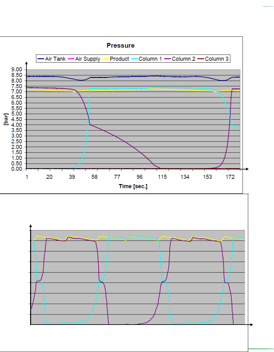
The PSA generator unit consist of two absorber columns working in alternate operation, e.g. the processes always runs in antiphrasis to one another in such way, that one absorber column with cleaned sieve delivers nitrogen, while the other absorber column regenerates saturated sieve. After a certain present period, the processes shifts, so that the first absorber column now regenerates saturated sieve, while the second is delivering nitrogen through a cleaned sieve. The nitrogen from the absorber column is stored in the product tank. After the product tank the pressure is regulated to 0 – 6 bar(g) depending upon the consumer’s specific working pressure. See picture 3 for more detailed information on the working process.
2-Column nitrogen PSA generator
The pressure drop ∆P on the accumulated nitrogen delivery must not exceed 0.5 bar(g).
Normal Process Sequence per column:
Pressurization and nitrogen delivery.
Pressure equalization (decreasing pressure).
Exhaust and purge with nitrogen (pressure drop causes oxygen release from sieve).
Pressure equalization.
HP-nitrogen PSA generator
Time
Picture 4. Schematics Pressure/Time diagram of Nitromat HP- nitrogen PSA generator
X-version nitrogen PSA generator
Pressure
- X-version PSA systems consist of X-number of single PSA units working in a counter phase. Total cycle time
of single PSA is divided by the number of generator units and cycling of each unit is shifted in time
Air Tank Air Supply Product Column 1 Column 2 Column 3 proportionally.
3.2 PSA generator parts description
3.2.1 PSA generator parts, 2-Column system
1. Absorber column 2. Cabinet containing electrical parts e.g. the PLC 3. Cycle pressure gauge 4. Valve for equalization of pressure 5. Valves for cycle operation 6. Valve for delivery of nitrogen to product tank 7. Feed air pressure regulator with filter 8. Air inlet 9. Outlet to product tank 10. Control valve block (solenoid valves)
11. Safety relief valves 12. Exhaust pipe (silencer)Absorber column
The absorbers column contains molecular sieve that concentrates nitrogen from air.
Control Cabinet
The cabinet contains all sensors, PLC, HMI and electrical parts.
Cycle Pressure Gauge
Indicate absorber column pressure during the unit cycles. Pressure is controlled by the feed air pressure regulator, which is set from factory. The gauge is able to read between 0 to 10.0 bar(g). Peak cycle pressure is 6.0 to 7.0 bar(g), unless specially modified by Oxymat to another pressure.
Axial / angle seated valve for equalization of pressure
After the pressurization cycle on each absorber column the equalization valve will open for a period of 10-20 sec. and pressure equalization between the absorber columns will take place.
Axial / angle seated valve for cycle operation
Axial / angle seated valve for delivery of nitrogen to nitrogen receiverThis valve opens while the absorber column is pressurized to deliver nitrogen to the product tank for use.
Feed air pressure regulator (without or with filter)
The regulator controls the feed air pressure to the absorber columns, which need adequate and stable feed air supply. Therefore an air tank is recommended to stabilize the air flow. The feed air pressure should not at any time drop below 7 bar(g) under operation. The feed air pressure regulator controls the inlet air pressure to 6 – 7 bar(g), unless specially modified by Oxymat to another pressure. If the regulator is without filter - Y strainer before regulator is presented.
The strainer removes rough internal impurities coming from the feed air tank and the pipe system.
Feed air inlet
The feed air inlet is connected to the feed air tank outlet.
Outlet to product tank
Nitrogen product tank and PSA generator are connected to this point. It is important to use the hose or pipe delivered from Oxymat A/S, as the internal dimension is an integrated part of system.
Control valve block (solenoid valves)
The valve block contains all solenoid valves, that via the PLC controls the pilot air supply to the process and drain valves.
Safety relief valves
These valves ensure that the pressure in tank / column does not exceed the design pressure.
Exhaust pipe Blow processed air.3.2.2 PSA generator parts, X-version system
X-version consists of X2 – X6 PSA generators connected into one inlet air manifold and one outlet nitrogen manifold. X-versions 3 to 6 are built as frame.
Nitrogen
outlet
Absorber column
Pressure gauge
Exhaust pipe
Safety valve
Picture 7. X-version PSA generator parts
Function of each component is similar to the functions of the components in a 2 column PSA plant.3.3 Coal tower parts description
Air from compressor, air dryer cleaned with filters enters the coal tower through the top and leaves through the bottom.
Coal tower
Inlet coal tower connection
Outlet coal tower connection
3.4 Air tank parts description
Air from coal tower enters the air tank through the bottom of the air tank and leaves through the top.
Pressure gauge
This should under normal condition read between 4.0 – 16.0 bar(g), depending on version
Air Tank
This stores the air for nitrogen PSA generator. The air tank provides stable flow for process.
Inlet air tank connection
Outlet air tank connection
Picture 9. Air tank parts
Pressure gauge 17. Air Tank 18. Inlet connection 19. Outlet connection

3.5 Product tank parts description
Product tank
This stores the nitrogen produced by the nitrogen generator. The product tank provides stable flow and purity of nitrogen.
Safety relief valve assembly with pressure outlet
Safety relief valve prevents excessive pressure from building up should a malfunction occur.
Pressure outlet on tee branch below the valve shall via the supplied hose be connected to the pressure transmitter on top of the control panel.
Inlet product tank connection
The nitrogen PSA generator is normally connected to the product tank at the bottom through ball valve.
Outlet product tank connection
On the top of the product tank is connected outlet for the consumption through a ball valve and a regulator.
Spare parts
Spare parts are delivered according customer request mentioned in OC.
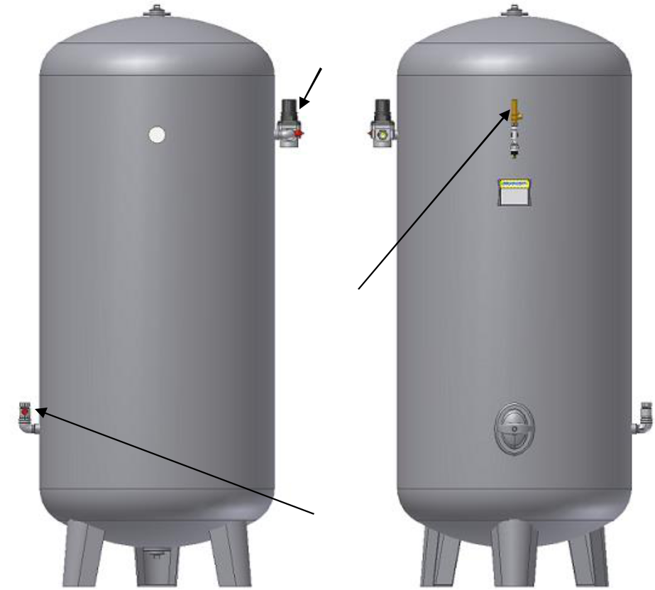
FRONT SIDE BACK SIDE
Picture 10. Product tank parts
Product tank 21. Safety relief valve assembly with pressure outlet
Inlet port with ball valve 23 outlet port with reduction valve
3.6 Connections
3.6.1 Coal tower connections
Air from compressor, air dryer cleaned with filters enters the coal tower through the top and leaves through the bottom.
Connections to/from coal tower
Model | Volume [l] | Connection [“] | Model | Volume [l] |
| Connection [“] |
type | Inlet |
| Outlet | type |
| Inlet | Outlet |
|
|
|
|
C010 | 10 | ¾” |
| ¾” | C020 | 20 |
| ¾” | ¾” |
|
|
|
|
|
|
|
|
|
|
C040 | 40 | 1” |
| 1” | C090 | 90 |
| 2” | 2” |
|
|
|
|
|
|
1½” |
| 1½” |
| 1½” | 1½” |
|
|
|
|
|
|
|
|
|
|
|
|
|
|
|
|
C150 | 150 | 2’’ |
| 2” | C230 | 230 |
| 2’’ | 2’’ |
|
|
|
|
|
|
|
|
|
|
C470 | 470 | 3 ½” |
| 3 ½” | C750 | 750 |
| 4” | 4” |
|
|
|
|
|
|
|
|
|
|
C1000 | 1000 | 6” |
| 6” | C1500 | 1500 |
| 6” | 6” |
|
|
|
|
|
|
|
|
|
|
|
| Table 2. | Air inlet connections to and from coal tower |
|
|
3.6.2 Air tank connections
Air from coal tower enters the air tank through the bottom of the air tank and leaves through the top.
Model | Volume [l] | Connection [“] | Model | Volume [l] | Connection [“] |
type | Inlet | Outlet | type | Inlet | Outlet |
|
|
AT090 | 90 | ¾” | ¾” | AT150 | 150 | ¾” | ¾” |
|
|
|
|
|
|
|
|
|
| ¾” | ¾” |
|
| ¾” | ¾” |
AT320 |
|
|
| AT470 |
|
|
|
320 | 1” | 1” | 470 | 1” | 1” |
|
|
|
|
|
|
|
|
|
| 1 ½” | 1 ½” |
|
|
|
|
|
|
|
|
|
|
|
|
|
|
|
|
|
|
|
| ¾” | ¾” |
|
|
|
|
|
|
|
|
|
|
|
|
|
| 1” | 1” |
|
|
|
|
|
|
|
|
AT750 | 750 | 1 ½” | 1 ½” | AT1000 | 1000 | 1 ½” | 1 ½” |
|
|
2” | 2” |
|
|
|
|
|
|
|
|
|
|
|
|
|
|
|
|
|
|
|
| 3 ½” | 3 ½” |
|
|
|
|
|
|
|
|
|
|
|
|
|
| 4” | 4” |
|
|
|
|
|
|
|
|
|
| 1 ½” | 1 ½” |
|
|
|
|
|
|
|
|
|
|
|
|
|
| 2” | 2” |
|
|
|
|
AT1500 |
|
|
| AT2000 |
|
|
|
1500 | 3 ½” | 3 ½” | 2000 | 1 ½” | 1 ½” |
|
|
|
|
|
|
|
|
|
| 4” | 4” |
|
|
|
|
|
|
|
|
|
|
|
|
|
| 6” | 6” |
|
|
|
|
|
|
|
|
|
|
|
|
AT3000 | 3000 | 2” | 2” |
|
|
|
|
|
|
|
|
|
|
2” | 1 ½” |
|
|
|
|
|
|
|
|
|
|
6.3 PSA generator connections
From pressure outlet on product tank to nitrogen pressure switch
Size of nylon tube, connecting product tank pressure outlet and pressure sensor on PSA generator control cabinet, depends on PSA generator model type.
Air inlet / nitrogen outlet connections
Air from air tank enters PSA generator through the bottom pipe set of PSA generator and nitrogen leaves through the top pipe set of PSA generator.
Air inlet connection / nitrogen outlet connection 2-columns
Model | Volume | Connection [“] | Model | Connection [“] |
type | [l] | Inlet | Outlet (note) | type | Inlet | Outlet (note) |
Nitromat N40ECO | 10 | ¾” | ⅜” (a) | Nitromat N40ECOHP | ¾” | ⅜” (a) |
|
|
|
|
|
|
|
Nitromat N75ECO | 20 | ¾” | ⅜” (a) | Nitromat N75ECOHP | ¾” | ⅜” (a) |
|
|
|
|
|
|
|
Nitromat N150ECO | 40 | ¾” | ⅜” (a) | Nitromat N150ECOHP | ¾” | ⅜” (a) |
|
½” (b) |
|
|
|
|
|
|
|
|
|
|
|
|
|
Nitromat N225ECO | 60 | ¾” | ⅜” (a) | Nitromat N225ECOHP | ¾” | ⅜” (a) |
|
|
|
|
|
|
|
Nitromat N350ECO | 90 | 1” | ¾” (c) | Nitromat N350ECOHP | ¾” | ½” (b) |
|
|
¾” | ¾” (c) |
|
|
|
|
|
|
|
|
|
|
|
|
Nitromat N600ECO | 150 | 1” | ¾” (c) | Nitromat N600ECOHP | 1” | ½” (b) |
|
|
|
|
|
|
|
Nitromat N800ECO | 230 | 1” | 1” (d) | Nitromat N800ECOHP | ¾” | ½” (b) |
|
|
|
|
|
|
|
Nitromat N1000ECO | 320 | 1 ½” | 1” (d) | Nitromat N1000ECOHP | 1” | ¾” (c) |
|
1 ½” (f) |
|
|
|
|
|
|
|
|
|
|
|
|
|
Nitromat N1850ECO | 470 | 1 ½” | 1 ¼” (e) | Nitromat N1850ECOHP | 1” | ¾” (c) |
|
1” (d) |
|
|
|
|
|
|
|
|
|
|
|
|
|
Nitromat N2650ECO | 750 | 1 ½” | 1 ½” (f) | Nitromat N2650ECOHP | 1 ½” | ¾” (c) |
|
1” (d) |
|
|
|
|
|
|
|
|
|
|
|
|
|
Nitromat N3150ECO | 1000 | 1 ½” | 1 ½” (f) | Nitromat N3150ECOHP | 1 ½” | 1” (d) |
|
|
|
|
|
|
|
Nitromat N4500ECO | 1500 | 2” | 1 ½” (f) | Nitromat N4500ECOHP | 1 ½” | 1” (d) |
Table 4. Air inlet connection to PSA generator and nitrogen outlet from PSA generator – 2-Columm
Air inlet / nitrogen outlet hose connection
Model | Connection [DN] | Model | Connection [DN] |
type | Inlet | Outlet (note) | type | Inlet | Outlet (note) |
Nitromat N1000X2-H | DN32 | DN15 (b) |
|
|
|
|
|
|
|
|
|
Nitromat N3150X2 | DN50 | DN40 (f) | Nitromat N4500X2 | DN50 | DN40 (f) |
|
|
|
|
|
|
Nitromat N3150HPX2 | DN50 | DN25 (d) | Nitromat N4500HPX2 | DN50 | DN25 (d) |
|
|
|
|
|
|
Nitromat N3150X3 | DN100 | DN50 (g) | Nitromat N4500X3 | DN100 | DN50 (g) |
|
|
|
|
|
|
Nitromat N4500X4 | DN100 | DN50 (g) | Nitromat N4500X5 | DN125 | DN65 (h) |
|
|
|
|
|
|
Nitromat N4500X6 | DN150 | DN100 (i) |
|
|
|


Table 5. Air inlet connection to PSA generator and nitrogen outlet from PSA generator – X-version The feed air quality must comply with ISO specification 8573-1:2010 class 2.4.1.NOTES (Connection from PSA generator outlet to product tank inlet):
For connection: supplied 10/12 ID/OD plastic tube to be used.
For connection: supplied 13/15 ID/OD plastic tube to be used.
For connection: use 20/22 ID/OD pipes of max 6 meters length, and material in Cu or AISI 314L, for use in nitrogen service.
For connection: use 25/28 ID/OD pipes of max 6 meters length, and material in Cu or AISI 314L, for use in nitrogen service.
For connection: use 32/35 ID/OD pipes of max 6 meters length, and material in Cu or AISI 314L, for use in nitrogen service.
For connection: use 39/42 ID/OD pipes of max 6 meters length, and material in Cu or AISI 314L, for use in nitrogen service.
For connection: use 50/54 ID/OD pipes of max 6 meters length, and material in Cu or AISI 314L, for use in nitrogen service.
For connection: use DN65 pipes of max 6 meters length, and material in Cu or AISI 314L, for use in nitrogen service.
For connection: use DN100 pipes of max 6 meters length, and material in Cu or AISI 314L, for use in nitrogen service.
7,0 - 10,0 bar(g) air supply from your compressor is connected to this fitting. Feed air (operating) temperature must be between 5°C minimum and 40°C maximum, T(O)-min / T(O)-max. Maximum allowable pressure P(S): 10.0 bar(g).
3.6.4 Product tank connections
Nitrogen from the PSA generator enters the product tank through the bottom, then nitrogen leaves product tank on the top consumption
Product tank connections
Model | Connection [“] | Model | Connection [“] |
type | Inlet |
| Outlet | type | Inlet | Outlet |
PT090 | ½” |
| ⅜” | PT150 | ½” | ⅜” |
|
|
| ¼” |
|
|
|
|
|
|
|
|
|
|
|
|
|
PT320 | ¾” |
| ½” | PT470 | ½” | ½” |
|
|
½” |
|
|
|
|
|
|
|
|
|
|
|
|
|
|
PT750 | ¾” |
| ¾” | PT1000 | 1” | 1” |
|
|
|
|
|
1” |
| 1” | 1½ “ | 1½ “ |
|
|
|
|
|
|
|
|
|
|
PT1500 | ¾” |
| ¾” | PT2000 | 1” | 1” |
|
|
|
1” |
| 1” |
|
|
|
|
|
|
|
|
|
|
|
|
PT3000 | 1½ “ |
| 1½ “ |
|
|
|
|
|
|
|
|
|
|
| Table | 6. | Connections | to / from product tank |
|
|
Warning: All tubes, hoses and piping must be compatible with oxygen and cleaned for oxygen service.
Sizes of air tank and product tank according model type of PSA generator
Model | PSA generator | Air tank [l] | Product tank [l] |
type | column size [l] |
|
|
Nitromat N40ECO | 10 | 20 | 20 |
|
|
|
|
Nitromat N75ECO | 20 | 40 | 60 |
|
|
|
|
Nitromat N150ECO | 40 | 80 | 120 |
|
|
|
|
Nitromat N225ECO | 60 | 120 | 180 |
|
|
|
|
Nitromat N350ECO | 90 | 180 | 270 |
|
|
|
|
Nitromat N600ECO | 150 | 250 | 375 |
|
|
|
|
Nitromat N800ECO | 230 | 460 | 690 |
|
|
|
|
Nitromat N1000ECO | 320 | 640 | 960 |
|
|
|
|
Nitromat N1850ECO | 470 | 940 | 1350 |
|
|
|
|
Nitromat N2650ECO | 750 | 1500 | 2000 |
|
|
|
|
Nitromat N3150ECO | 1000 | 2000 | 3000 |
|
|
|
|
Nitromat N4500ECO | 1500 | 3000 | 4000 |
|
|
|
|
Nitromat N1000X2-H | 320 | 750 | 1000 |
|
|
|
|
Nitromat N3150X2 | 1000 | 1000 | 1000 |
|
|
|
|
Nitromat N4500X2 | 1500 | 1500 | 1500 |
|
|
|
|
Nitromat N4500X3 | 1500 | 1500 | 1500 |
|
|
|
|
Nitromat N4500X4 | 1500 | 1500 | 1500 |
|
|
|
|
Nitromat N4500X5 | 1500 | 1500 | 1500 |
|
|
|
|
Nitromat N4500X6 | 1500 | 1500 | 1500 |
|
|
|
|
Table 7. Minimum sizes of air and product tank3.7 Control system
Power/OFF
Switch for turning the power supply ON or OFF. This is placed on the side of the cabinet
Touch Screen
Finger operated Touch screen – see instruction manual for touch screen control system in attached CD.
Display control
See instruction manual for display control system in attached CD.
Emergency stop button
In case of emergency you can manually stop PSA generator
Picture 11. Control panel with small touch screen- IntelliControl, Display Control Panel DCP0 27. Power/OFF 28. Touch screen 29. Display contro
Picture 12. Control panel with small touch screen – Display Control Panel DCP1, Panel Control 6” PC2 27. Power/OFF 28. Touch screen 30. Emergency stop button
For further detailed information – see separate Control system manual in attached CD.
4 Installation
4.1 Unpacking
You should have received the Nitromat nitrogen PSA generator and the Instruction manual needed for proper installation of the unit. The nitrogen product tank (if supplied) is shipped separately.
Place and unpack the shipment at the pre-determined location with a hard plane and level surface, and check if the delivery is complete according to shipment and delivery lists. If any packages or parts are missing, notify the Freight Company and Oxymat A/S at once. The manufacturer is not liable in loses caused during shipment.
Warning: Lifting lugs on tanks / columns, if present, are only for handling of the tanks / columns if they are detached from the PSA unit. The PSA unit is not to be lifted by the lifting lugs on columns or by the pipes. The nitrogen PSA generator must be lifted by the skid, with a suitable lifting device operated by a certified or trained operator. Take the necessary precautions to avoid units tipping over during handling.
The PSA generator columns must be pressurized to protect the molecular sieves from ambient moisture.
Important: Upon receiving your Nitromat nitrogen PSA generator, inspect the unit thoroughly for signs of damage. Any signs of damage, either external or internal, should be noted on the delivery receipt, and also reported immediately to both the Freight Company and Oxymat. Contact Oxymat at Tel +45 4879 7811 / Fax +45 4879 7813 or Tel +421 32 779 0123 / Fax +421 32 779 0125. The manufacturer is not liable in damage caused during shipment.
4.2 Pre-installation instructions
It is necessary to consider the location, space available, air supply, and power supply prior to installing your Nitromat nitrogen PSA generator.
Important: for safe installation and operation etc. of compressor, air dryer or other equipment refer to manuals concerned for the equipment.
4.2.1 Location
Climatic requirements:
The PSA generator must be located in a well-ventilated indoor area which remains above 5°C and below 45°C T(S). Operating the PSA generator in an area below 5°C or above 45°C, could cause damage not covered under the manufacturer warranty.
Physical PSA generator characteristics (space requirement) for 2-Column system:
Physical PSA generator characteristics 2-column
Model | Floor | Height | Load | Model | Floor | Height | Load |
space | space |
type | [cm] | [kg] | type | [cm] | [kg] |
[cmxcm] | [cmxcm] |
|
|
|
|
|
|
Nitromat N40 | 55x45 | 156 | 75 | Nitromat N40 HP | 55x45 | 156 | 75 |
|
|
|
|
|
|
|
|
Nitromat N75 | 65x50 | 147 | 115 | Nitromat N75 HP | 65x50 | 153 | 115 |
|
|
|
|
|
|
|
|
Nitromat N150 | 65x50 | 146 | 145 | Nitromat N150 HP | 65x50 | 144 | 145 |
|
|
|
|
|
|
|
|
Nitromat N225 | 65x50 | 195 | 200 | Nitromat N225 HP | 65x50 | 195 | 200 |
|
|
|
|
|
|
|
|
Nitromat N350 | 90x80 | 186 | 250 | Nitromat N350 HP | 90x80 | 183 | 250 |
|
|
|
|
|
|
|
|
Nitromat N600 | 90x80 | 222 | 370 | Nitromat N600 HP | 90x80 | 219 | 370 |
|
|
|
|
|
|
|
|
Nitromat N800 | 90x80 | 216 | 450 | Nitromat N800 HP | 90x80 | 214 | 450 |
|
|
|
|
|
|
|
|
Nitromat N1000 | 130x95 | 223 | 700 | Nitromat N1000 HP | 130x90 | 223 | 700 |
|
|
|
|
|
|
|
|
Nitromat N1850 | 130x95 | 228 | 1100 | Nitromat N1850 HP | 130x95 | 226 | 1100 |
|
|
|
|
|
|
|
|
Nitromat N2650 | 200x125 | 238 | 1870 | Nitromat N2650 HP | 200x125 | 236 | 1870 |
|
|
|
|
|
|
|
|
Nitromat N3150 | 200x125 | 246 | 2000 | Nitromat N3150 HP | 200x125 | 244 | 2000 |
|
|
|
|
|
|
|
|
Nitromat N4500 | 200x125 | 295 | 2400 | Nitromat N4500 HP | 200x125 | 293 | 2400 |
Table 8. 2C PSA generator characteristics
Physical PSA generator characteristics (space requirement) for X-versions:
Physical PSA generator characteristics X-version
Model | Floor | Height | Load* | Model | Floor | Height | Load* |
space | space |
type | [cm] | [kg] | type | [cm] | [kg] |
[cmxcm] | [cmxcm] |
|
|
|
|
|
|
Nitromat N1000X2-H | 260x90 | 219 | 1400 | Nitromat N3150X2 | 200x250 | 244 | 4600 |
|
|
|
|
|
|
|
|
Nitromat N4500X2 | 200x250 | 295 | 6600 | Nitromat N3150X3 | 455x244 | 290 | 9000 |
|
|
|
|
|
|
|
|
Nitromat N4500X3 | 455x244 | 290 | 9000 | Nitromat N4500X4 | 606x244 | 290 | 12000 |
|
|
|
|
|
|
|
|
Nitromat N4500X5 | 606x244 | 290 | 15000 | Nitromat N4500X6 | 606x244 | 290 | 18000 |
|
|
|
|
|
|
|
|
| Table | 9. X- | version PSA generator characteristics |
|
|
Physical product tank characteristics (space requirements).Product tank sizes
Model type |
| Volume [l] / Diameter [mm] | Model type | Volume [l] / Diameter [mm] |
PT090 |
| 90 / 300 | PT150 | 150 | / 400 |
|
|
|
|
|
|
PT320 |
| 320 | / 500 | PT470 | 470 / 600 |
|
|
|
|
|
|
PT750 |
| 750 | / 750 | PT1000 | 1000 / 863 |
|
|
|
|
|
|
PT1500 |
| 1500 / 863 | PT2000 | 2000 | / 1100 |
|
|
|
|
|
|
|
PT3000 |
| 3000 | / 1280 |
|
|
|
|
|
|
|
|
Table | 10. Size of product tank. Please, consult Oxymat for further details. |
|
Exhaust pipe connections in mm:
Exhaust pipe connections
Model type | Diameter Ø [mm] | Model type | Diameter Ø [mm] |
Nitromat N40 | 150 | Nitromat N40 HP | 150 |
|
|
|
|
Nitromat N75 | 150 | Nitromat N75 HP | 150 |
|
|
|
|
Nitromat N150 | 150 | Nitromat N150 HP | 150 |
|
|
|
|
Nitromat N225 | 150 | Nitromat N225 HP | 150 |
|
|
|
|
Nitromat N350 | 150 | Nitromat N350 HP | 150 |
|
|
|
|
Nitromat N600 | 150 | Nitromat N600 HP | 150 |
|
|
|
|
Nitromat N800 | 150 | Nitromat N800 HP | 150 |
|
|
|
|
Nitromat N1000 | 150 | Nitromat N1000 HP | 150 |
|
|
|
|
Nitromat N1850 | 150 | Nitromat N1850 HP | 150 |
|
|
|
|
Nitromat N2650 | 250 | Nitromat N2650 HP | 250 |
|
|
|
|
Nitromat N3150 | 250 | Nitromat N3150 HP | 250 |
|
|
|
|
Nitromat N4500 | 250 | Nitromat N4500 HP | 250 |
Table 11. Exhaust pipe connections
4.2.2 Air Supply (Feed Air)
Air from your compressor or feed air supply must be less than 40°C, T(O)-max, before it reaches the nitrogen PSA generator. High feed air (operating) temperature will reduce the performance of the nitrogen PSA generator and will cause damage not covered under the manufacturer's warranty. Low feed air (operating) temperatures may cause freezing of components and damage not covered under the manufacturer's warranty.
Warning: The compressor, air tank or other feed air supply and pressurized equipment must be fitted with adequate protective devises to protect against exceeding allowable limits of the concerned equipment e.g. safety relief valves. Feed air supply must be protected against exceeding 10 bar(g) the maximum allowable pressure P(S) for Nitromat nitrogen PSA generators. The safety relief valves on PSA generator columns and product tank (if supplied) are solely for the protection of these components.
The feed air quality must comply with ISO specification 8573-1:2010 class 2.4.1., e.g. maximum number of particles per m³ is as following:
|
| Maximum number of the particles per m³ |
| Moisture |
|
| Residual Oil |
|
|
|
|
|
|
|
class |
|
| Particle size, d [μm] |
|
| Max. pressure |
|
| Max. |
|
|
|
|
|
|
| dew point |
|
| concentration |
|
|
| d ≤ 0,1 | 0,1 < d ≤ 0,5 | 0,5 < d ≤ 1,0 | 1,0 < d ≤ 5,0 |
|
|
|
|
|
|
| (PDP) [°C] |
|
| [mg/m³] |
|
|
|
|
|
|
|
|
|
|
|
0 |
| As specified by the equipment, user or supplier and more stringent than class1 |
|
1 |
| Not specified | ≤ 20 000 | ≤ 400 | ≤ 10 |
| - 70 |
|
| 0,01 |
|
2 |
| Not specified | ≤ 400 000 | ≤6000 | ≤ 100 |
| - 40 |
|
| 0,1 |
|
3 |
| Not specified | Not specified | ≤ 90 000 | ≤1000 |
| - 20 |
|
| 1 |
|
4 |
| Not specified | Not specified | Not specified | ≤ 10 000 |
| + 3 |
|
| 5 |
|
5 |
| Not specified | Not specified | Not specified | ≤ 100 000 |
| + 7 |
|
| > 5 |
|
Table 12. Feed air quality
Dew point +3°C & residual water content max. 6 g/m³ and residual oil content max. 0,01 mg/m³.Warning: Use only hoses and pipes of correct size and suitable for operating pressure and fluid. Never use hoses, which are frayed, damaged or worn. Always use the correct type and size of connections. Make sure hoses are depressurized before disconnecting.
The connections of hoses, if used must be are done with high quality connection systems, e.g. a clamp system or compression end fittings depending on the type of hose applied. It is not recommended to use ordinary hose clips.
Important: All hoses and piping must be routed out of harm’s way and secured to prevent accidental pulling of hoses piping or connections.
The hose/piping used to bring air from the compressor to the air tank and from the air tank to the nitrogen PSA generator should be dimensioned to supply the needed feed air flow at a pressure between 6,0 - 10,0 bar(g). By 12,5 bar version: max.12 bar(g). The dimensions must at least be:
Minimum dimensions on feed air hoses/pipes
Model type | Dimensions [“] | Model type | Dimensions [“] |
Nitromat N40ECO | ¾” | Nitromat N40ECO HP | ¾” |
|
|
|
|
Nitromat N75ECO | ¾” | Nitromat N75ECO HP | ¾” |
|
|
|
|
Nitromat N150ECO | ¾” | Nitromat N150ECO HP | ¾” |
|
|
|
|
Nitromat N225ECO | ¾” | Nitromat N225ECO HP | ¾” |
|
|
|
|
Nitromat N350ECO | ¾” | Nitromat N350ECO HP | ¾” |
|
1” |
|
|
|
|
|
|
|
Nitromat N600ECO | 1” | Nitromat N600ECO HP | 1” |
|
|
|
|
Nitromat N800ECO | 1” | Nitromat N800ECO HP | ¾” |
|
|
|
|
Nitromat N1000ECO | 1½” | Nitromat N1000ECO HP | 1” |
|
|
|
|
Nitromat N1850ECO | 1½” | Nitromat N1850ECO HP | 1” |
|
|
|
|
Nitromat N2650ECO | 1½” | Nitromat N2650ECO HP | 1½” |
|
|
|
|
Nitromat N3150ECO | 1½” | Nitromat N3150ECO HP | 1½” |
|
|
|
|
Nitromat N4500ECO | 2” | Nitromat N4500ECO HP | 1½” |
|
|
|
|
X-version |
|
|
|
Nitromat N1000X2-H | 1 ¼” | Nitromat N3150ECOX2 | 2” |
|
|
|
|
Nitromat N4500ECOX2 | 2” | Nitromat N3150HPX2 | 2” |
|
|
|
|
Nitromat N4500HPX2 | 2” | Nitromat N3150X3 | 4” |
|
|
|
|
Nitromat N4500ECOX3 | 4” | Nitromat N4500ECOX4 | 4” |
|
|
|
|
Nitromat N4500ECOX5 | 5” | Nitromat N4500ECOX6 | 6” |
|
|
|
|
Table 13. Air inlet connections
With a properly dimensioned hose/piping1, the feed air pressure must not be less than 6 bar(g) at inlet point during operation. The use of an improperly size of hose/piping will result in reduced nitrogen generating capacity.
It is recommended to have a shut off valve installed where the air inlet hose/piping is connected to the compressed air supply or if present on the air tank to facilitate safe depressurization of the hose/piping before removal of connections.
Max length of hose: 3 meters
4.2.3 Power supply
Warning: The interior of the cabinet contains electrical parts that may produce electrical hazard if not handled properly. To prevent electrical shock, care must be taken when servicing this equipment. In general electrical installation and servicing is to be performed by trained or authorized personnel only.
110-240V, 50-60Hz, single phase, 1.0A
Proper voltage must be provided to the generator at all times. Maximum fuse on power supply 10A
Improper voltage will cause damage not covered under the manufacturer's warranty. To protect your PLC on the generator Oxymat recommend the use of electrical filters.
Power should be supplied to the unit from a grounded electrical outlet with a 3-prong plug. It is recommended to use a circuit that will not be accidentally turned off, as this will cause the unit to stop cycling. If power supply is off and the unit is being used, the product tank will depressurize.
In order to prevent production stop and purity drop in case of electric power failure, a UPS (power backup) is recommended as an option.
4.3 Installation
Unpacking and handling in general
On receipt of the aggregate, check that the individual parts correspond with those listed on the delivery note.
When unloading, check immediately for possible damage to all parts, such as dents, scratches, corrosion, torn electric cables, bent pipes, or the like. In case of defects or damage, the carrier and supplier shall be informed immediately.
The aggregate shall only be lifted according to suppliers instructions, and in case of compressor/air dryer delivery, special care must be taken to the instructions noted in the compressor/air dryer suppliers manual. In order to avoid squeezing of instruments, piping, etc., use a suitable lifting device.
Warning: The PSA generator columns must be pressurized to protect the sieves from ambient moisture.
Placement of aggregate:
Place all the main parts in their final positions on hard, plane and level surfaces. Make sure that sufficient space between parts is available for maintenance and inspection. Up-line the parts to proper horizontal and vertical positions and anchor all parts to the concrete floor by means of anchor bolts or like.
Warning: Exhaust gas from the nitrogen PSA generator can contains more than 30 % oxygen and can be oxidizing. Exhaust gas must be led by piping or ducts piped out of the room to the outdoor atmospheric air. Failure to do this may cause serious damage, injury or death. The room where the PSA generator is located must always be well ventilated.
OPTIONAL - For on-line back-up or surge needs, we recommend that backup nitrogen is connected directly on the nitrogen outlet pipe (through a check valve), and that the pressure on the backup nitrogen is approximately 0.3 kg/cm2 below the regulator setting on the nitrogen PSA generator.
Warning: Make sure that your back-up/emergency nitrogen supply is installed with a nitrogen pressure regulator, the pressure must be max. 7.0 bar(g), unless specially modified by Oxymat to higher pressure. Check valves must be fitted on both backup nitrogen supply and nitrogen outlet from product tank.
Very important: Check all fittings for leak using a suitable leak detecting fluid.
Make all the installations and note the cautions mentioned above.
Configuration: New or existing - compressor, air dryer, coal tower with oil mist absorber, feed air tank; new nitrogen PSA generator; new or existing product tank, high pressure compressor
1.1 For the compressor installation – follow the instructions in the compressor supplier’s manual – read this manual before installation!!!
1.2 Connect air hose/pipe from compressor outlet to air dryer inlet
1.3 Connect air hose/pipe from air dryer outlet via the pre-filter and the micro-filter (new or existing) to the inlet port at the top of the coal tower.
1.4 Connect the coal tower (oil mist absorber) equipped with a second micro-filter to the inlet of air tank. The coal tower inlet is placed on top of the tower, and the outlet is placed at the bottom of the tower
If the air tank is an integrated part of the compressor, the coal tower location is after the air tank, and the auto drain valve is in this case placed on the side of the air tank instead of the bottom of the tank
1.5 Connect air hose/pipe from bottom of coal tower to the bottom of the air tank.
1.6 Connect air hose/pipe from an upper port on air tank to inlet of PSA generator.
1.7 Connect nitrogen hose/pipe from PSA generator outlet to the nitrogen product tank bottom valve
1.8 Also connect your nitrogen application/consumption to the pressure regulator on top of the product tank
1.9 In case we have high pressure compressor, connect nitrogen hose/pipe from product tank to high pressure compressor. Always check type of connection to high pressure compressor before installation.
Very important: Inspect every piece of safety device for defects, correct installation and function.
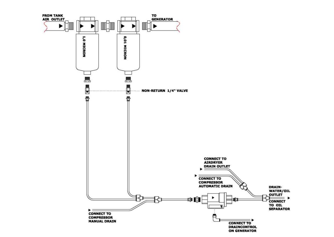
Very important: Installation connections between supplied parts and existing equipment follow sizing instructions.Optional drain system might be available.
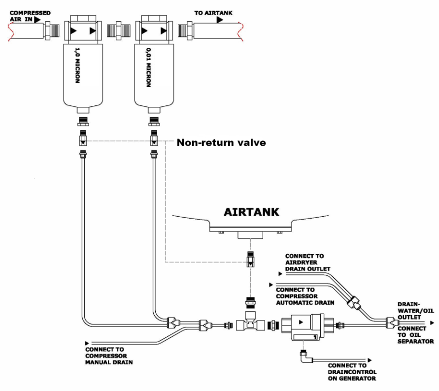
Picture 13. Drain system – separate air tank
Picture 15. Instruments hose connection
Instruments hose connection – for more information follow wiring diagram
5 Operation
5.1 Initial start-up procedure
To start the nitrogen PSA generator for the first time, follow the steps below:
Remove transport brackets at the air dryer (if present).
Turn on the power supply to the air dryer (if present).
Allow the refrigeration air dryer temperature to stabilize at the pre-set value +3°C
Remove transport brackets at the compressor (if present).
Turn on the power supply to the compressor (if present).
Make sure, that all shut off valves between the plant items are open
Let the compressor keep running and observe that the compressor shifts to unloaded operation, when the compressor pressure has reached the pressure stop set point.
Carefully and gentle open for feed air supply to the PSA generator.
Turn on the electric power supply to the PSA generator.
Switch the mode selector to manual position.
Ensure that the drain system works properly by checking, that exhaust air appears from the drain water outlet for about 1.5 second every 5 minutes.
Be aware that air and condensate might be exhausted automatically from compressor and air dryer during start up – this is not a mal function.
Shut off the nitrogen application/consumption and prepare for Leak test:
Let the plant run in manual mode, until the nitrogen product tank pressure reaches a minimum of 5 bar(g).
Turn the mode selector switch to stop/off, and the PSA generator will stop after a little while, when the actual operation cycle is completed.
Shut off the feed air supply.
If fitted with purity monitoring probe close of the pressure reduction valve on probe inlet.
Read and note the pressure P1 in nitrogen product tank, column 1, column 2 and air tank.
Let the plant stand still (rest) and isolated in pressurized condition for an hour.
After an hour read and note the pressure P2 in nitrogen product tank, column 1, column 2 and air tank.
Then determine an eventually pressure drop as the difference between P1 and P2 for each component.
The Leak test is OK, if the pressure drop after one hour pressurized isolation is less than 0.1 bar(g). In case of leaks they must not cause more than 0.1 bar(g) pressure drop per hour.
Reset the pressure reduction valve on probe inlet.
To obtain the design purity in nitrogen product tank purge the tank with nitrogen as follows:
Check that nitrogen consumption is closed off.
Open up for flow from feed air supply/compressor.
Start the feed air supply/compressor.
Start the PSA generator and let it run for about 15 minutes.
Check that pressure in nitrogen product tank reaches the value stated in Design Review Certificate.
Open for nitrogen consumption. Adjust flow to approximately to 50 % of design flow (refer to Design Review Certificate).
Let the PSA generator run in manual mode until design purity is reached. Duration 0.5 - 8 hours depending on purity and capacity.
When design purity is reached close off nitrogen consumption switch PSA generator to auto mode and let the PSA generator run until it stops automatic. This should occur within 10 minutes. If the PSA generator does not stop as described refer to section for pressure set point procedure.
At the end of this period, observe the feed air pressure gauge and the cycle pressure gauge on the PSA generator for at least 5 complete cycles, to make sure that the PSA generator starts and stops within the allowable limits, as follows:
Observe that the feed air pressure should be no less than 7.0 bar(g) unless stated otherwise by manufacture.
Observe that the peak cycle pressure should not increase above 7.0 bar(g) unless stated otherwise by manufacture (Design Review Certificate).
Now the plant is ready for normal operation.
For X-version repeat procedure for all PSA separately.
Important: When the PSA generator is being started up for the first time, or after a long shut-down period, it is possible that the nitrogen product tank is full of air. Before the PSA generator can supply nitrogen of design purity, any air in the nitrogen product tank must be purged.
Purge / delivery function
in case that purity control is delivered, purge/delivery functions as follow:
Purging starts if level of oxygen in product is higher than level set in start purge parameter. Pressure in product tank has to be higher than pressure set in min. purge pressure parameter. During purging purge valve is opened and delivery valve is closed. If pressure in product tank drops below value set in min. purge pressure parameter purge valve is closed and also delivery valve is still closed. If level of oxygen in product drops below level set in start purge parameter, purge valve is closed and delivery valve is opened.
Warning: Always vent nitrogen outdoor. Nitrogen concentrations higher than 78 % in the air can without warning cause serious personal injury or death.
Product purity (N2) – indicate the purity in the product tank. The purity is controlled by purity alarm. If the purity level drops below the alarm settings, an alarm is executed. If the purity level drops below the purity stop settings, then the PSA will perform a controlled stop.
Product gas quality – please consider, that Oxymat is choosing most suitable filters to reach required product gas quality. If filters are supplied by another supplier, Oxymat cannot guarantee product gas quality.
5.2 Operation
The Nitromat nitrogen PSA generator can operate in either auto or manual mode or can be in stand-by mode. The operation mode is selected on the mode selector switch.
Refer to touch screen control manual.5.3 Shut-Down
1 Turn of nitrogen application/consumption
Close off central nitrogen application/consumption. This will insure that the nitrogen product tank is full the next day even if a nitrogen discharge valve is left open.
Ensure that the mode selector switch is in the AUTO position, and wait until the PSA generator stops cycling. This allows the product tank to fill completely with nitrogen for immediate use required. It also allows the unit to shut down at the proper point in the cycle.
NOTE: Failure to wait or immediate or accidental stop of operation during a cycle will result in temporary lower nitrogen purity during subsequent use.
2 Turn off Power
Turn the selector switch to stand-by position.
Turn off the compressor power switch (if present).
Turn off the air dryer power switch (if present)
Turn off the PSA generator power switch
5.4 Normal Start-up
Turn on the air dryer power supply (if present) and run the dryer.
Allow the refrigeration air dryer temperature to stabilize at the pre-set value +3°C
Turn on the compressor power supply (if present), or open for the central compressed feed air supply.
Observe that the feed air pressure is above the minimum pressure requirements.
Turn on the power supply to the nitrogen PSA generator.
Turn the mode selector switch in manual position.
Observe that the drains are working
Observe that the peak cycle pressure do not excess the value stated Design Review Certificate.
Turn the mode selector switch in auto position.
After a while observe that the PSA generator automatically stops, when the nitrogen product tank pressure reaches pressure set point stop, stated by manufacture in Design Review Certificate.
To shut down the Nitromat nitrogen PSA generator for 24 hours or longer, complete all steps in Section –
Shutdown. In addition perform the following:
Fully close all manual valves to isolate the nitrogen in the nitrogen product tank, to prevent the loss of pressure in the nitrogen product tank, in order to enable a normal start-up. Turn off all electric powers, e.g. on compressor, air dryer and generator.
Keep columns pressurized and sealed to protect contained sieve against ambient moisture.
If PSA generator is fitted with purity monitoring probe, close of the pressure reduction valve on probe inlet.
5.6 Start-up after an Extended Shut-Down
After an extended shutdown or an unexpected shutdown, such as an electric power failure, you must purge the nitrogen product tank of any low purity nitrogen before the nitrogen PSA generator can supply nitrogen within the purity specifications.
To purge the nitrogen product tank, follow step 14 in section – Initial start-up procedure.
6 Maintenance
Warning: The interior of the cabinet contains electrical parts that may produce electrical hazard if not handled properly. To prevent electrical shock, care must be taken when servicing this equipment. In general electrical installation and servicing is to be performed by trained or authorized personnel only.
Monitoring the operation of the unit on a regular schedule is the best way to insure a long life for your Nitromat nitrogen PSA generator. External and internal inspection of tanks/columns and other pressurized equipment must be carried out according to local regulations.
Refer to the concerned manuals of the equipment for service instructions
6.1 Daily inspection
Every day observe the operation of the nitrogen generator system
Observe that the filter drain port and air tank drain port is not clogged. Air should discharge from these ports (or the end of the tubes if connected) for 3 seconds every 3 to 7 minutes (according to ambient air humidity) when the PSA generator is cycling.
Do also observe your air supply system on daily basis, check oil level and operating temperature on the compressor, and check function of your refrigeration air dryer as well as filter elements placed after the refrigeration air dryer, the pressure gauges on the filter elements must not be in red area at any time of operation.
Clogging of the drain systems will cause water/oil carry-over into the absorber columns, and will cause severe damage to the adsorbent which is not covered under the manufacturer’s warranty.
Refer to the concerned manuals of the equipment for service instructions.
6.2 Weekly inspection
The weekly inspection of the nitrogen generator system consists of a daily inspection point, plus:
Air compressor maintenance (clean procedure of air/oil after-cooler)
Air dryer maintenance (clean procedure of cooler)
Gas analyser sensor maintenance
After-cooler clean procedure
6.3 Biannual PM – or every 4 000 working hours
The half-year Preventive Maintenance of the nitrogen generator system consists of:
Service of air compressor according to supplier manual (filters and oil replacement, etc...)
Service of air dryer according to supplier manual (drain and strainer cleaning, etc...)
Replacement of pre-filter 0,1μm and micro filter element 0,01μm
6.4 Annually PM – or every 8 000 working hours
The Annual PM of the unit consists from the points of half-year PM, plus:
Air package maintenance according to manufacturer manual
Coal tower maintenance- replace active coal, oil indicator and micro-filter cartridge
PSA generator - whole system has to be inspected for function, damage, leakage (solenoid valve block, hose/pipe connection, safety valves, etc...); process valves has to be cleaned and properly re-greased (recommended lubricant SuperLube® PTFE silicone grease); inspection of strainer and main regulator; gas analyser maintenance / calibration; inspection of level and status of the molecular sieve
– replacement of 2” O-ring
6.5 2 years maintenance – or every 16 000 working hours
The 2 years PM consists from the points of annual PM, plus:
Replacement of top brass filters
Replacement of process valves
Replacement of main inlet pressure regulator
Replacement of fan for control cabinet - if present
Oxymat A/S * Fasanvej 18-20 * DK- 3200 Helsinge
6.6 3 years maintenance – or every 24 000 working hours
The 3 years PM consists from the points of annual and 2 years PM, plus:
6.7 5 years PM – or every 40 000 working hours
The 5 years PM consist from points of annual PM, plus:
6.8 Filter element replacement
The expected life of the pre-filter elements is 6 months or 4.000 working hours with proper maintenance of air compressor.
The expected life of the micro filter elements is 6 months or 4.000 working hours with proper maintenance of air compressor and pre-filters.
It is recommended to replace active coal in carbon tower, yearly. At the very latest – when the oil indicator mounted on carbon tower turns red.
Improper compressed air quality could affect the operation of your nitrogen generator. The filter element(s) supplied with each unit have been selected by manufacturer based upon the units feed air requirements.
Caution: The following will cause damage not covered under the manufacturer’s warranty:
Water, oil, rust, scale and/or other foreign objects carryover in the feed air can damage filter elements and/or plugged drains.
Warning: Oxymat filter elements have been selected based upon their ability to function in severe operating conditions. Use of other than original equipment manufacturer filters could cause damage not covered under the Oxymat warranty.
Warning: Do not attempt to remove the filter bowls unless the units cycle pressure gauge reads zero and the rubber hose from the filter elements is disconnected slowly to release pressure.
Note that the first filter from the air inlet port is the pre-filter and the second filter is the micro filter.Filter element replacement
Close off feed air supply to PSA generator.
Carefully disconnect the 4/6 mm rubber drain tube the bottom of the filter to depressurize.
Turn the filter element counter clockwise and remove the element.
Remove check valve form old filter element and install the check valve on the new filter element.
Install new filter element with check valve.
Reconnect tube to the check valve at the bottom of the filter element.
Perform a leak test.
Coal tower annual maintenance
Stop Nitromat PSA generator and air compressor
Close the manual ball valves behind the air dryer and front of the air tank
Depressurize unit (open safety relief valve slightly)
Disconnect hose/piping connection from the coal-tower
Remove top filter unit (turn it counter clockwise)
Use a suitable vacuum cleaner and suck out all the active coal
Perform a tower maintenance
Use a suitable funnel and fill the tower with new active coal (leave approx. 8-10cm free space on top of the tower)
Refit the top filter unit applying a new sealing
Refit hose/piping connection
Close manual ball valve on the bottom of tower and remove micro filter element
Pressurize the tower from top to approx. 5 bar and after pressure is reached, totally discharge tower through manual bottom ball valve
Repeat this procedure until the coal dust is completely blown out from the tower
Install new filter element and replace oil indicator
Start the system and perform a leak test
6.9 Tank / column maintenance
Warning: Tanks must be depressurized and purged thorough with air to remove all nitrogen before service or inspection. Always vent nitrogen to outdoor atmospheric air. Sources of nitrogen must be positively blinded or disconnected before service or inspection. Never rely on a closed valve. Tank atmosphere must be analysed for safe oxygen content before inspection.
Examples of disconnecting or blinding of nitrogen sources:
Generator columns: Disconnect feed air supply and nitrogen product tank.
Nitrogen product tank: Disconnect PSA generator nitrogen outlet, nitrogen backup and nitrogen consumption.
External and internal inspection of tanks/columns and other pressurized equipment must be carried out according to local regulations.
If molecular sieve is going to be replaced inspect columns for corrosion or other damage. Replace if needed.
Refer to sieve material safety data sheet for handling and safety instructions of sieve.
Product tank should be inspected internal every 4 years or according to local regulations.
6.10 Valve maintenance
All valves should be inspected, cleaned and lubricated within period of 12 months or after 8.000 operating hours. Important notice: Upper and lower equalization valves require initial maintenance after 2000 hours of operation. After this, it can follow the normal maintenance frequency.
Valve cleaning and lubrication
Stop the nitrogen PSA generator.
Close off feed air supply to PSA generator.
Close and disconnect product tank.
Depressurize the columns by opening safety valves.
NOTE! The columns must never be left unpressurized more than 2 hours.
Carefully disconnect and remove the upper and lower pipe set.
Seal the inlets of the columns by using tape to avoid any contamination of column content by the moist.
Disassemble the pipe sets and disassemble the valves.
Remove all the particles, dirt, residual oil etc. from inside the valve.
Clean and lubricate the valve (recommended lubricant SuperLube® PTFE silicone grease).
Reinstall the valve as well as the pipe sets.
Perform a leak test.
6.11 Safety devices
Visual inspect safety relief valves and other safety devices for dirt or damage.
If there is debris in the valve seat scavenge the valve as follows: Pressurize tank/column and loosen the top screw one turn to. This should remove debris from the valve. Retighten the top screw.
Always wear personal protection of hearing, hands, eyes etc.
6.12 Service check list
When performing the stated monitoring/maintenance, it will be an advantage to follow and use the Service check list shown on next page.
Service Check List
| Type: ________________________________________________________ | Installation | every 4 000 hours | every 8 000 hours | every 16 000 hours | every 24 000 hours | every 32 000 hours | every 40 000 hours |
| Series no: _____________________ Hour meter: ____________________ |
|
|
|
|
|
|
|
|
|
|
|
|
|
|
|
|
|
1. | Service compressor according to suppliers instructions | x | x | x | x | x | x | x |
|
|
|
|
|
|
|
|
|
2. | Check of refrigeration air dryer incl. drain according to suppliers instructions | x | x | x | x | x | x | x |
|
|
|
|
|
|
|
|
|
3. | Check of pressure in air tank, column tanks and product tank | x | x | x | x | x | x | x |
4. | Check of cycle time and cycle interval | x | x | x | x | x | x | x |
5. | Check of product purity | x | x | x | x | x | x | x |
6. | Check of product consumption (flow) | x | x | x | x | x | x | x |
7. | Check of drain system | x | x | x | x | x | x | x |
8. | Replace filters (pre- and micro filter) |
| x | x | x | x | x | x |
9. | Replace micro-filter after coalescing tower |
|
| x | x | x | x | x |
10. | Replace active coal and oil indicator yearly (recommended) |
|
| x | x | x | x | x |
11. | Replace micro filter and sterile filter/bacterial filter |
|
| x | x | x | x | x |
12. | Inspection of pressure regulator |
| x | x |
| x |
| x |
13. | Replacement of pressure regulator |
|
|
| x |
| x |
|
14. | Cleaning of strainer |
| x | x | x | x | x | x |
15. | Cleaning and inspection of process valves |
|
| x |
| x |
| x |
16. | Replacement of process valves |
|
|
| x |
| x |
|
17. | Check level and status of molecular sieve |
| x | x | x | x | x |
|
18. | Replacement of molecular sieve recomended / on demand |
|
|
|
|
|
| x |
19. | Leak test | x | x | x | x | x | x | x |
20. | Check of safety valves | x | x | x | x | x | x | x |
21. | Replacement of top brass filters |
|
|
| x |
| x | x |
22. | Check of manometers | x | x | x | x | x | x | x |
23. | Check of pipe and hose connections, cables, plugs etc. | x | x | x | x | x | x | x |
24. | Check of solenoid valve block, leakage/function | x | x | x | x |
| x | x |
25. | Replacement of solenoid valve block |
|
|
|
| x |
|
|
26. | Check of purity analyser. Calibrate if required | x | x | x | x |
| x | x |
27. | Replacement of purity analyser |
|
|
|
| x |
|
|
28. | Control of product consumption / flow | x | x | x | x | x | x | x |
29. | Fan filter replacement |
| x | x | x | x | x | x |
30. | Fan replacement |
|
|
| x |
| x |
|
31. | Affixing of service sticker |
| x | x | x | x | x | x |
32. | Hand over copy of service check list to the client |
| x | x | x | x | x | x |
33. | Fill in timesheet incl. spare parts list | x | x | x | x | x | x | x |
Remarks to client:
Date:
Service technician:

Table 14. Service part list
7 Troubleshooting
Most common operation failure is insufficient nitrogen purity due to inadequate flow rate (capacity) caused by too heavy leakage or other capacity problems. If a purity problem occurs, it is strongly recommended at once to uncover these eventually problems before any other initiative are taken – so follow the Route Diagram shown below:
|
|
|
|
|
|
|
|
| Purity |
|
|
|
|
|
|
|
|
|
|
|
|
|
|
| Problem |
|
|
|
|
|
|
|
|
|
|
|
|
|
|
|
|
|
|
|
|
|
|
|
|
|
|
|
|
|
|
|
| Yes | No |
|
|
|
|
|
|
|
|
|
| Flow Problem |
|
|
|
|
| OK |
|
|
|
|
|
|
|
|
|
|
|
|
|
|
|
|
|
|
|
|
|
|
|
|
|
|
|
|
|
|
|
|
|
|
|
|
|
|
|
|
|
| Leak Test |
|
|
|
|
|
|
|
|
|
|
|
|
|
|
|
|
|
|
|
|
|
Capacity |
|
|
|
|
|
|
| Leaks present |
|
|
|
|
|
|
|
|
|
|
|
|
|
|
|
|
|
|
|
|
|
|
|
|
|
|
|
|
|
|
|
|
|
|
Test |
|
|
|
|
|
|
|
|
|
|
|
|
|
|
|
|
|
|
|
|
|
|
|
|
|
|
|
|
|
|
|
|
|
|
|
|
|
|
|
|
| No | Yes |
|
|
| Leaks |
|
|
|
|
|
|
|
|
|
|
|
|
|
|
|
|
|
|
|
|
|
|
|
|
|
| Removal |
|
Corrections |
|
|
|
|
|
|
|
|
|
|
|
|
|
|
|
|
|
|
|
|
|
|
|
|
|
|
OK |
|
|
|
|
|
|
|
|
|
|
|
|
|
|
|
|
|
|
|
|
|
|
|
|
|
|
|
|
|
|
|
|
|
|
|
|
|
|
|
|
|
|
|
|
|
|
|
|
|
|
|
| Run Generator |
|
|
| Check Sensor |
|
|
|
|
|
|
No Yes |
|
| in Manual |
|
|
| (if present) |
|
|
|
|
|
|
|
|
|
| Mode |
|
|
| Calibrate/replace |
|
|
|
|
|
|
|
|
|
|
|
|
|
|
|
|
|
|
|
|
|
|
|
|
|
|
|
|
|
|
|
|
|
|
|
|
|
|
|
|
|
|
|
|
|
|
| Purity |
|
|
|
|
|
|
|
|
|
|
|
|
|
|
| Problem |
|
|
|
|
|
|
|
|
|
|
|
|
|
|
|
|
|
|
|
|
|
|
|
|
|
|
|
|
|
|
|
|
|
|
|
|
|
|
|
|
|
|
| | | | | | | | | | |
7.1 Leak test procedure
Shut off the nitrogen application/consumption.
Let the plant run in manual mode, until the nitrogen product tank pressure reaches a minimum of 5 bar.
Turn the mode selector switch to stand-by/off, and the PSA generator will stop after a little while, when the actual operation cycle is completed.
Shut off the feed air supply.
If coal tower is installed, close of oil indication tube. If fitted with purity monitoring probe close of the pressure reduction valve on probe inlet.
Read and note the pressure P1 in nitrogen product tank, column 1, column 2 and air tank.
Let the plant stand still (rest) and isolated in pressurized condition for an hour.
After an hour read and note the pressure P2 in nitrogen product tank, column 1, column 2 and air tank.
Then determine an eventually pressure drop as the difference between P1 and P2 for each component.
The Leak test is OK, if the pressure drop after one hour pressurized isolation is less than 0.1 bar. In case of leaks they must not cause more than 0.1 bar pressure drop per hour.
If closed open for coal tower oil indication tube and reset the pressure reduction valve on probe inlet to 1.0 bar
7.2 Air regulator adjustment procedure
Unlock lock on adjustment knob.
To increase pressure turn clockwise.
To decrease pressure turn counter clockwise.
Make small adjustments and let system cycle through one cycle before making another adjustment.
If readings are still incorrect, make another adjustment until you are within manufacturer's specifications stated in Design Review Certificate.
7.3 Capacity test procedure
Close the shut off valve between the PSA generator and the nitrogen product tank.
Read and note the pressure in the nitrogen product tank – called the starting pressure: P1 (bar).
Rapidly open the shut off valve between the nitrogen product tank and the nitrogen application/consumption and rapidly close it again after exactly one minute. This will achieve the real and exact consumption for a one minute period.
Now read and note the final pressure P2 (bar).
Determine the capacity by using the formula: (P1 – P2) x (Volume of nitrogen product tank in litres) = capacity in litres per minute. Check the result with the stated capacity in the Design Review Certificate.
7.4 Pressure set point procedure
The pressure in the nitrogen product tank controls start and stop of PSA generator in auto mode.
Determination the nitrogen product tank peak pressure P1:
Switch PSA generator to manual mode
Shut off nitrogen consumption.
Let the PSA generator run for 10 minutes or more.
Read and note the maximum nitrogen product tank pressure during this period. This is the peak pressure P1.
Calculating stop set point pressure and restart hysteresis set point:
Calculate the stop set point pressure P2 by subtracting 0.05 bar from peak pressure P1.
P2 = P1 - 0.05.
The hysteresis set point (normal value 0.5 bar) controls when the PSA generator restarts.
Example: Measured peak pressure P1: 6.50 bar
Stop set point pressure P2 = P1 - 0.05 = 6.50 - 0.05 = 6.45 bar
With hysteresis set to 0.5 bar the PSA generator will restart when the pressure in nitrogen product tank has decreased 0.5 bar. Restart at = P2 - 0.50 = 6.45 - 0.50 = 5.95 bar
How this start and stop process is adjusted and controlled depends on PSA generator control system type. The above mentioned nitrogen product tank pressures must be read out and adjusted according to system. For PSA generators equipped with small or large touch screen control system refer to the control system manuals in attached CD.
7.5 Probe Check and Calibration
Nitromat nitrogen PSA generators with control system have a probe for monitoring the purity of produced nitrogen.
Procedure for checking the probe depends on the type of probe fitted.
See probe type on information label inside control panel.
If present the probe module is placed in the lower control cabinet.
Zirconium probes:
Warning: The entire probe module and especially the heater block can get very hot. Touching these parts may cause burns. The module can still be very hot even after the module has been turned off. Always wait for at least 30 minutes before touching the module.
Important:
Do not touch the sensor’s ceramic probe.
Do not blow cold air or gas onto the sensor when it is warm.
Do not bend or tear the twisted steel pipe.
For further detailed information – see separate Control system manual and Sensor manual as separate file.
7.6 Purging procedure
To obtain the design purity in nitrogen product tank purge the tank with nitrogen as follows:
Check that nitrogen consumption is closed off.
Open up for flow from feed air supply/compressor.
Start the feed air supply/compressor.
Start the PSA generator and let it run for about 15 minutes.
Check that pressure in nitrogen product tank reaches the value stated in Design Review Certificate.
Open for nitrogen consumption. Adjust flow to approximately to 50 % of design flow (refer to Design Review Certificate).
Let the PSA generator run in manual mode until design purity is reached. Duration 0.5 - 8 hours depending on purity and capacity.
When design purity is reached close off nitrogen consumption switch PSA generator to auto mode and let the PSA generator run until it stops automatic. This should occur within 10 minutes. If the PSA generator does not stop as described refer to section for pressure set point procedure.
8 Scrapping
8.1 Dismounting
By the time when the equipment is no longer in use - dismount as follows:
Dismount, remove and collect all electronics into an electronics scrap pile
Disconnect, remove and collect all hoses and other plastics into a plastic scrap pile
Empty absorber columns from the molecular sieve, and fill it into bags.
Dismount all pipes and sort all metal parts into steel or Cu scrap piles.
Collect all organic, flammable materials into a separate scrap pile.
Dispose the different categories of waste in a via designated collection facilities appointed by the government or local authorities according to local regulations. Correct disposal and recycling will help preventing potential negative consequences to the environment and human health.
8.2 Disposal
The molecular sieve is a nontoxic organic material, which can be disposed along with the rest of sorted scrap.
However the disposal must be done according to national and local laws and rules.
Refer to material safety data sheet for correct handling of molecular sieve and proper personal protection.List of shortcuts
PSA | pressure swing adsorption |
MDD | medical device directive |
2C | 2-column PSA generator |
MSDS | material safety data sheet |
T(O) | operating temperature |
T(S) | max. allowable temperature |
PLC | programmable logic controller |
HMI | human-machine interface |
OC | order confirmation |
ID/OD | inlet diameter/outlet diameter |
P(S) | max. allowable pressure |
HP | High purity |
|
|
|
|
|
Conversion table [DN] – [inch] |
|
DN10 |
|
| ⅜“ |
|
DN15 |
|
| ½” |
|
DN20 |
|
| ¾” |
|
DN25 |
|
| 1” |
|
DN32 |
|
| 1 ¼” |
|
DN40 |
|
| 1 ½” |
|
DN50 |
|
| 2” |
|
DN65 |
|
| 2 ½” |
|
DN80 |
|
| 3” |
|
DN90 |
|
| 3 ½” |
|
DN100 |
| 4” |
|
DN125 |
| 5” |
|
DN150 |
| 6” |
|
Table 15. | Conversion table of dimensions DN – inch |
Conversion from bar to Pascal:
1bar = 105 Pa

Click vào nút tài liệu để download tài liệu pdf máy tạo khí nito